Add a road
The following chapter provides an overview on adding road geometry and the most common types of road features.
1 Adding a single digitized road
Single digitized roads have one road bed. Direction of travel could be 1- or 2-way. To add a single digitized road:
1.1 Connected to an existing road
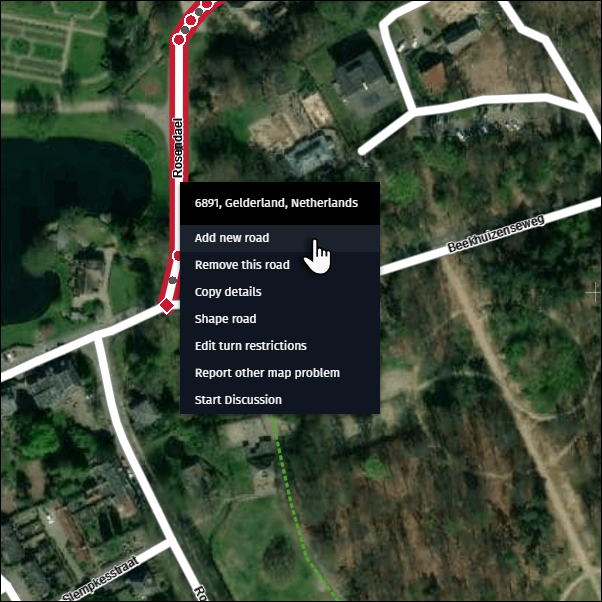
1) Zoom to the location where you want to add a new road.
2) Right-click on an existing road and select “Add new road”.
1.2 Connected to an existing node or shape point
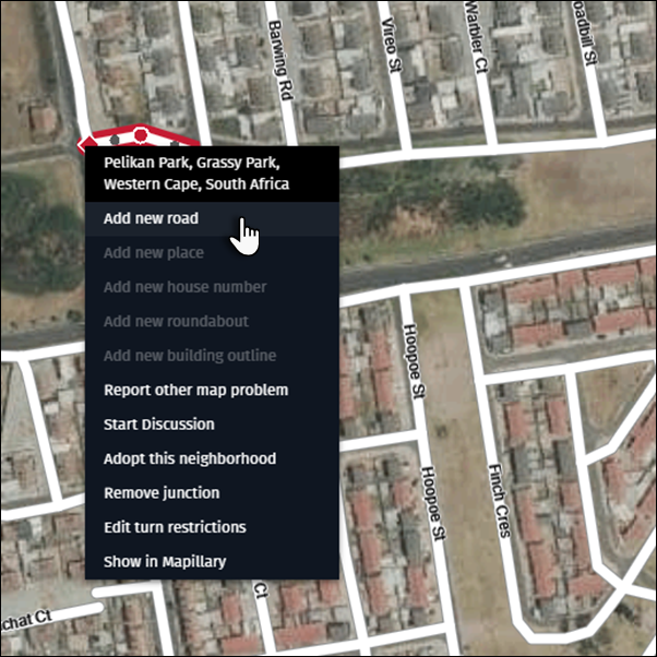
1) Zoom to the location where you want to add a new road.
2) Right-click on an existing node or shape point and select “Add new road”.
1.3 From a location within the map
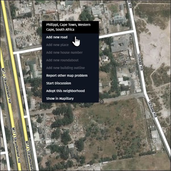
1) Zoom to the location where you want to add a new road.
2) Right-click on the location within the map and select “Add new road”.
1.4 From the activation bar
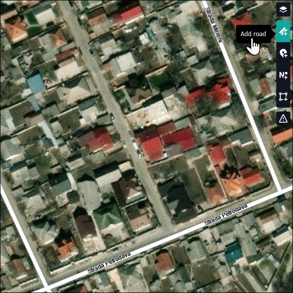
1) Zoom to the location where you want to add a new road.
2) Click on the “Add road” button in the activation bar and add the road to the map.
A few points to keep in mind when adding geometry:
1) When adding a road, follow the road’s center line (the median axis of the roadbed).
2) Each click inserts a new shape point. Use shape points to accurately represent the road’s shape.
3) Use shape points sparingly to avoid wobbling and incorrect representation.
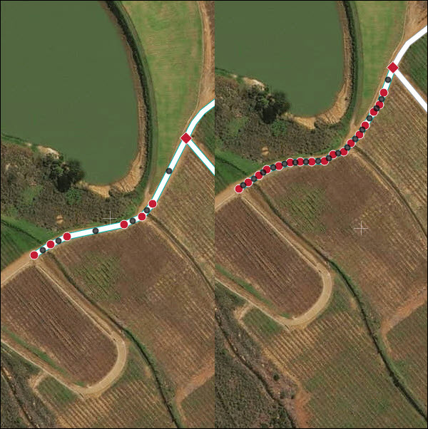
4) When finished adding the road, double click at the location where the road ends.
5) If the newly added road crosses any existing roads, a pop-up window appears asking for the crossing type of the two roads.

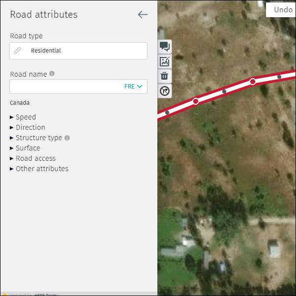
6) Add more information about the new road segment in the “Road attributes” panel.
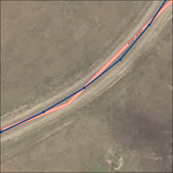
2 Adding a multi digitized road
A multi digitized road is a road with the two opposing directions of travel digitized separately. Typically, multi digitized roads can be identified by the following:
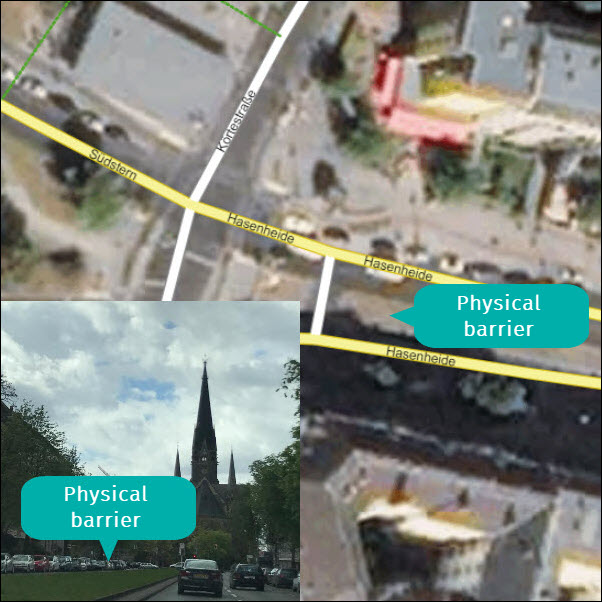
- A significant solid line or physical barrier separates the road into two road beds with opposing directions of travel.
- A significantly wide road bed (+ 50 m) exists in reality.
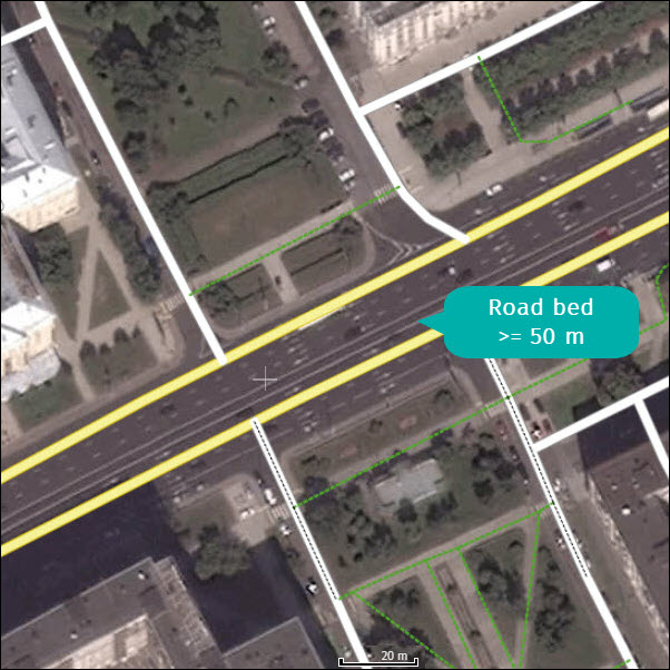
If one of these road characteristics is present, add the road as multi digitized:
1) Separately digitize two road beds (one for each direction of travel). Follow the roadbed’s center line.
2) Add the correct direction of travel to the new road segments.
3) Add the same street name(s) to the new road segments.
4) Adjust other road attributes for both sides as needed.
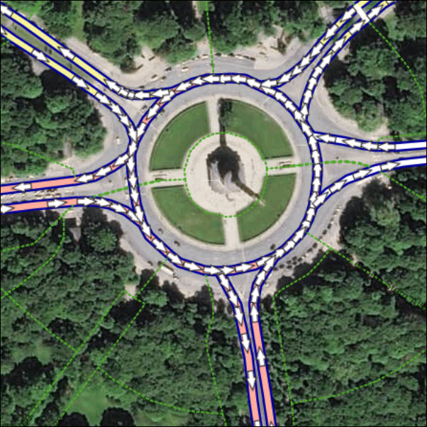
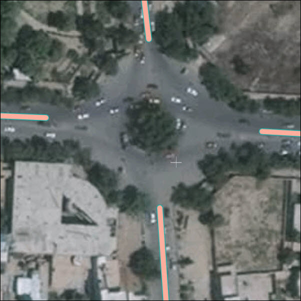
3 Adding a roundabout
Roundabouts are traffic features characterized by the following:
- A circular or oval road shape.
- The direction of travel is the same for the complete loop (counter-clockwise in right-side driving countries and clockwise in left-side driving countries).
- The roundabout has three or more roads connected to it.
To add a roundabout, zoom to level 18 or higher.
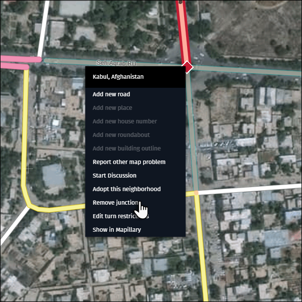
If a junction already exists where there should be a roundabout:
1) Remove the junction by selecting one of the connecting roads and right-clicking on its end node. In the pop-up menu, select “Remove junction”.
2) Move the the road outside of the roundabout.
3) Repeat this step for all other roads.
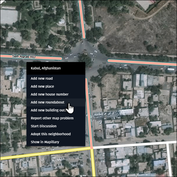
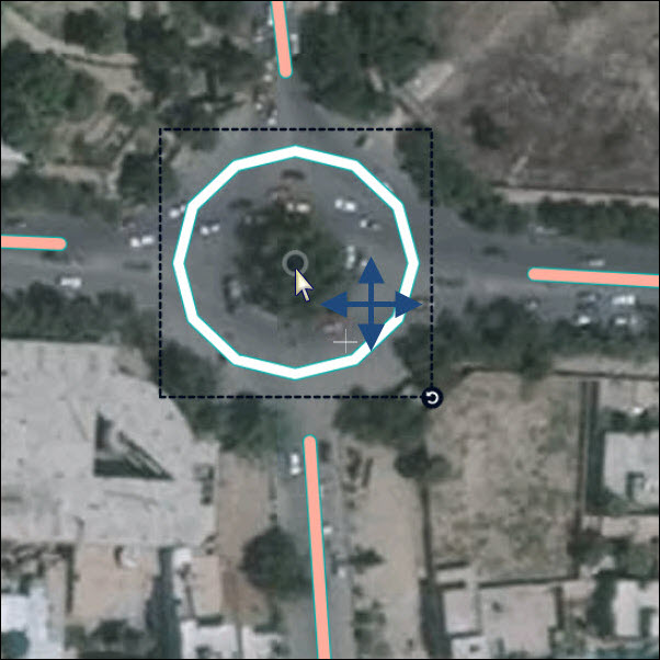
4) Right click on the center of the new roundabout and select “Add new roundabout.” A resizable roundabout sketch appears.
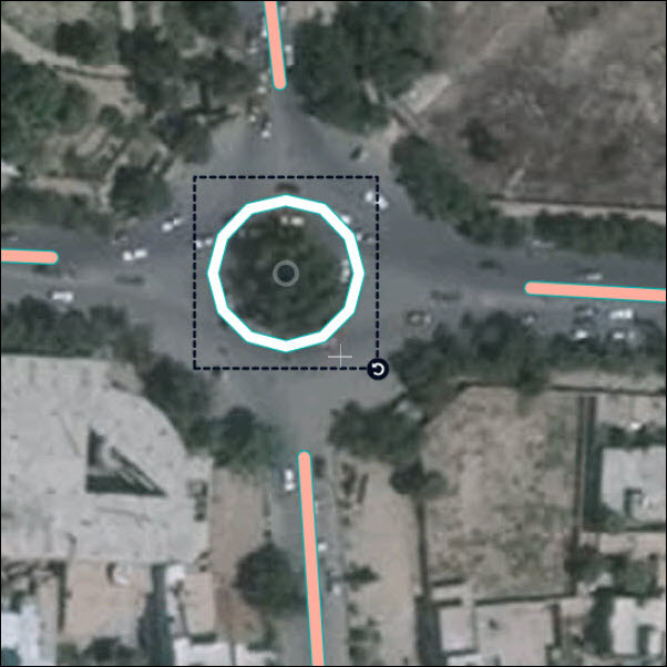
5) Adjust the dotted frames of the roundabout sketch to the center lines of the roundabout as reflected in the satellite imagery.
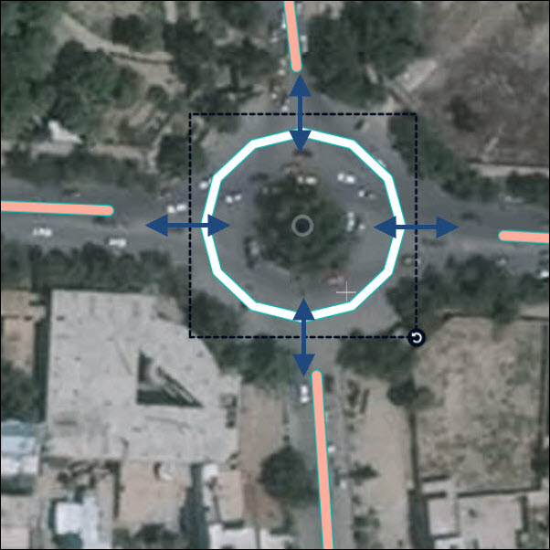
6) Adjust the position of the roundabout sketch by dragging the center point to the center of the roundabout in reality.
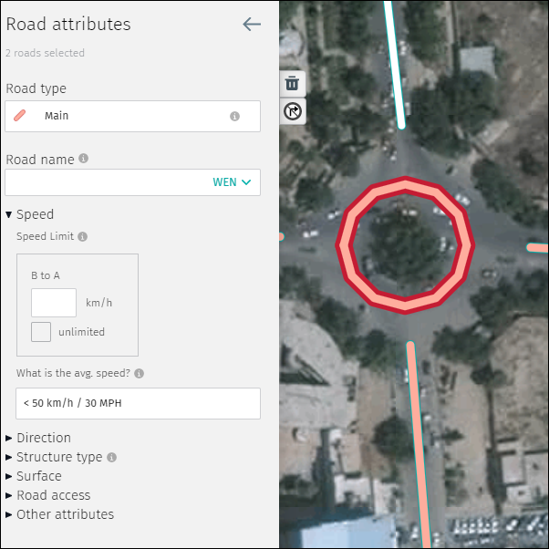
7) Make all relevant attribute edits to the roundabout before re-connecting roads.
- Highlight the two roundabout segments by clicking one segment, hold “Shift” and click on the other segment.
- The “Road type” should match the highest Road type of the connecting roads (e.g. if “Local access” and “Residential” road types connect to the roundabout, the roundabout should receive “Local access” Road type).
- If no speed information is known then use speed information from the connecting road with the lowest speed.
- If the roundabout has a name, add it.
- Do not add route numbers to the roundabout.
- The direction of travel is automatically set according to the driving regulations in the country.
- Edit other attributes as necessary.
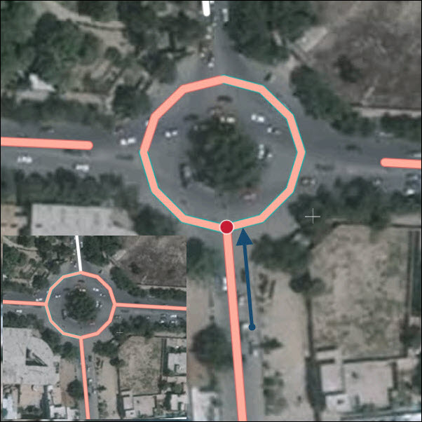
8) Re-connect roads to the new roundabout:
- Click on one of the side roads.
- Move the node to the point it connects to the roundabout.
- Repeat for all connecting roads.
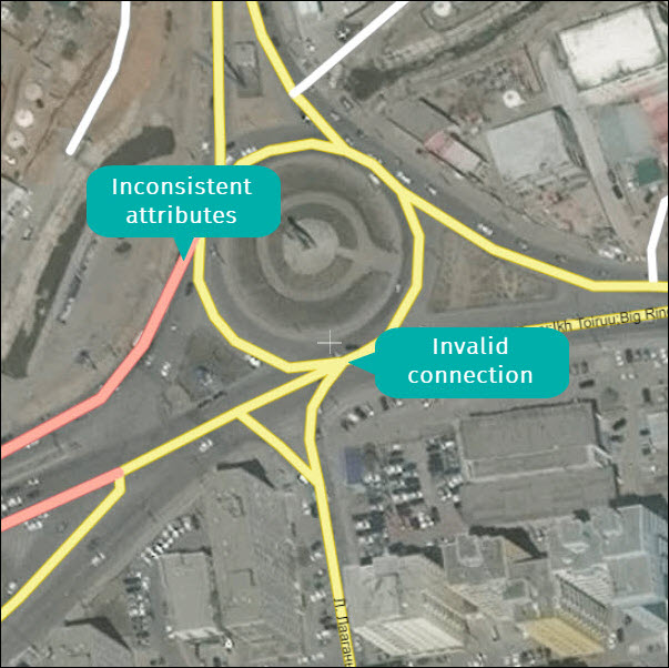
Note:
- Do not connect multiple roads to the same node on the roundabout
- Be careful to maintain consistency of the roundabout attributes and connected roads (e.g. Road Type, Speed Limit/Category, Lane Category, etc.).
4 Define crossings
Accurately defining crossings is necessary for correct routing. If you create a new road segment that crosses another road or if the new road is near another road then Map Creator will ask you to define a crossing type. There are three options:
- “Intersects with the other road” when roads meet at grade.
- “Is an overpass” when a road passes above another road.
- “Is an underpass” when a road passes below another road.
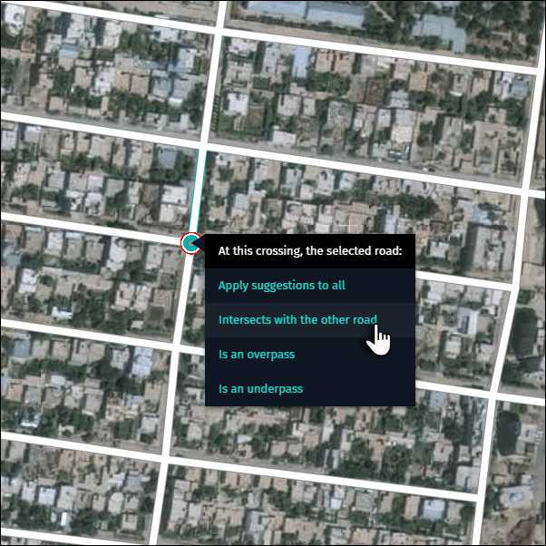
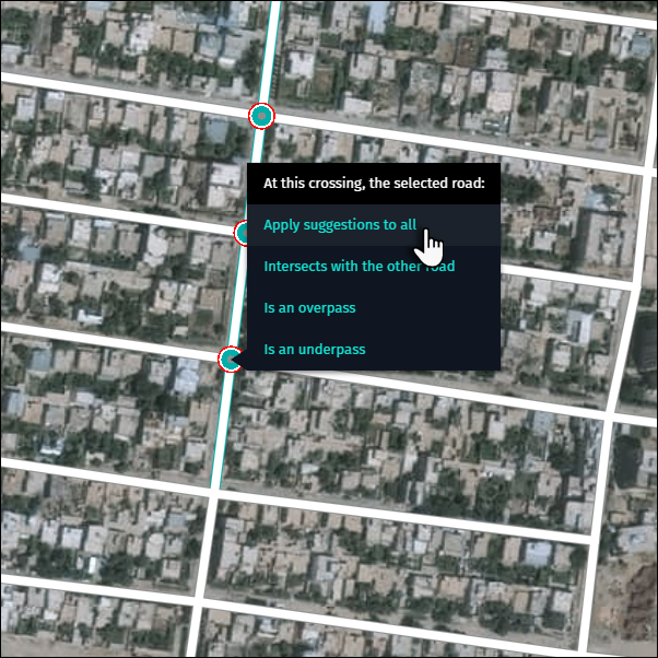
If multiple roads are crossed when adding a new road you can click “Apply suggestions to all” to apply the same crossing type to all newly created crossings.
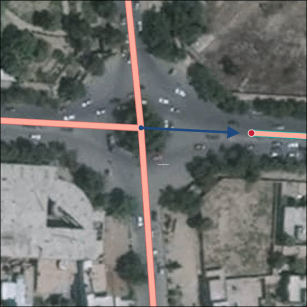
5 Accurately representing intersections
Accurately representing intersections is critical for correct routing. When creating new intersections, consider the type of routing guidance a driver requires to navigate the intersection safely. Below are a few examples of different types of intersections and how they should be represented in Map Creator.

6 Turn restrictions and divider
Add turn restrictions in Map Creator when they are present in reality and not conflicting with an existing divider (see end of the chapter).
Three types of turn restrictions can be edited:
- No continuation allowed.
- No right turn allowed.
- No left turn allowed.
To activate turn restrictions you need to make a left mouse click on the road segment.
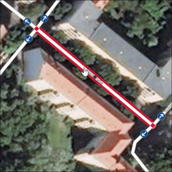
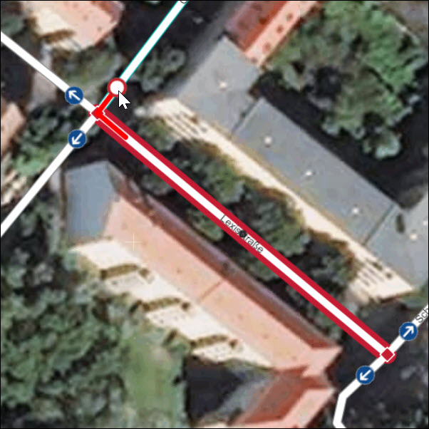
Once turn restrictions are displayed, follow these steps to edit:
1) Hover your mouse over the icon to identify the driving direction. This is indicated by a line on the road segment:
- blue line = allowed driving direction, and
- red line = forbidden driving direction.
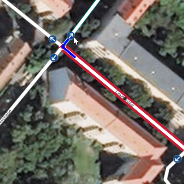
2) Click on the icon and toggle between “allowed” and “forbidden”:
- blue circle with white arrow = allowed maneuver, and
- red circle with white filling = forbidden maneuver.
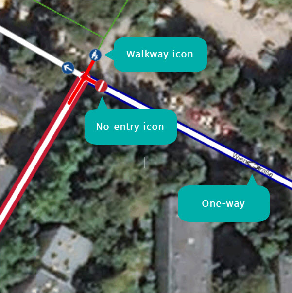
In some situations turn restrictions cannot be modified because the maneuver is restricted by default. A couple of examples:
- a walkway is connected to a junction, or
- a one way road with oncoming traffic exists.
Another feature complement turn restrictions are divider. In reality, a divider can be a solid line or a small physical wall/barrier along the center line of the road bed. In Map Creator, divider are displayed by a black dotted line. They are not editable.
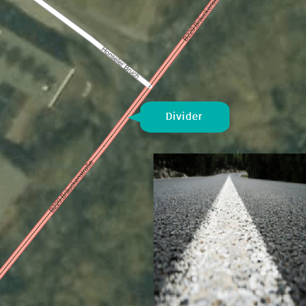
In case you see a divider in the map, then this may imply already information about forbidden turns at an intersection. This depends if the intersection/divider is considered as closed or open which is at the moment not possible to distinguish via the display. If you enter a turn restriction in addition to a closed intersection/divider, then your edit will be reviewed because of doubled information. The image below gives you an overview about closed and open intersections/divider.
